📡 Fish Finder Cone Angle Calculator
Calculate sonar coverage width at any depth based on transducer cone angle & frequency
| Cone Angle | 10 ft (3 m) | 20 ft (6 m) | 40 ft (12 m) | 60 ft (18 m) | 100 ft (30 m) | 200 ft (61 m) |
|---|---|---|---|---|---|---|
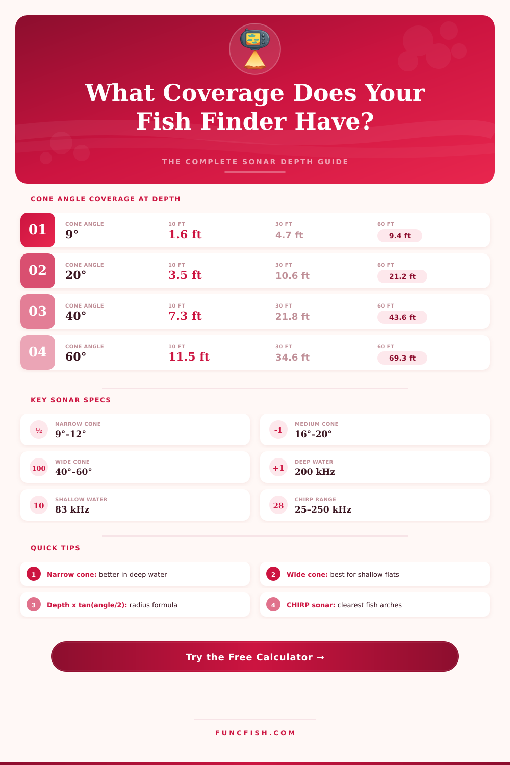
| 9° | 1.6 ft / 0.5 m | 3.1 ft / 1.0 m | 6.3 ft / 1.9 m | 9.4 ft / 2.9 m | 15.7 ft / 4.8 m | 31.4 ft / 9.6 m |
| 12° | 2.1 ft / 0.6 m | 4.2 ft / 1.3 m | 8.4 ft / 2.6 m | 12.6 ft / 3.8 m | 21.0 ft / 6.4 m | 42.0 ft / 12.8 m |
| 20° | 3.5 ft / 1.1 m | 7.1 ft / 2.2 m | 14.2 ft / 4.3 m | 21.3 ft / 6.5 m | 35.5 ft / 10.8 m | 71.0 ft / 21.6 m |
| 40° | 7.3 ft / 2.2 m | 14.5 ft / 4.4 m | 29.1 ft / 8.9 m | 43.6 ft / 13.3 m | 72.7 ft / 22.2 m | 145.3 ft / 44.3 m |
| 60° | 11.5 ft / 3.5 m | 23.1 ft / 7.0 m | 46.2 ft / 14.1 m | 69.3 ft / 21.1 m | 115.5 ft / 35.2 m | 231.0 ft / 70.4 m |
| 83° | 17.8 ft / 5.4 m | 35.6 ft / 10.9 m | 71.2 ft / 21.7 m | 106.8 ft / 32.5 m | 178.0 ft / 54.2 m | 356.0 ft / 108.5 m |
| Target Species | Typical Depth | Recommended Cone | Best Frequency | Coverage at Depth |
|---|---|---|---|---|
| Largemouth Bass | 5–25 ft (1.5–7.6 m) | 40°–60° | 83 kHz | 7–30 ft wide |
| Walleye | 15–45 ft (4.6–13.7 m) | 20°–40° | 83/200 kHz | 10–30 ft wide |
| Striped Bass (Offshore) | 80–200 ft (24–61 m) | 9°–12° | 200 kHz | 12–40 ft wide |
| Catfish | 10–40 ft (3–12 m) | 20°–40° | 83 kHz | 7–30 ft wide |
| Crappie / Panfish | 4–15 ft (1.2–4.6 m) | 40°–60° | 83 kHz | 5–18 ft wide |
| Trout (Stream) | 2–10 ft (0.6–3 m) | 40°–83° | 83 kHz | 3–18 ft wide |
| Pike / Muskie | 10–30 ft (3–9 m) | 20°–40° | 200 kHz | 7–22 ft wide |
| Halibut (Offshore) | 100–500 ft (30–152 m) | 9°–12° | 50/200 kHz | 16–100 ft wide |
| Frequency | Max Depth | Beam Width | Detail Level | Best Use |
|---|---|---|---|---|
| 50 kHz | 5,000 ft (1,524 m) | 35°–45° | Low | Deep sea, offshore trolling |
| 83 kHz | 1,000 ft (305 m) | 60° | Medium | Shallow lakes, panfish |
| 200 kHz | 600 ft (183 m) | 16°–20° | High | All-purpose freshwater |
| 455 kHz | 300 ft (91 m) | 35° | Very High | Side imaging, shallow detail |
| 800 kHz | 150 ft (46 m) | 3°–6° | Extreme | Down imaging, dock fishing |
| CHIRP (25–250) | 3,000 ft (914 m) | Varies | Superior | Best all-around clarity |
A sonar beam begin at the transducer’s face and spreads out into a cone shape as the beam travel through the water. The cone angle of the transducer determine the width of the beam. If the cone angle of the transducer are too wide for the depth of the water, the sonar image will appearing blurry.
If the cone angle of the transducer is too narrow for the depth of the water, the sonar beam will not show area to the sides of the beam. Therefore, understanding the cone angle allow people to see the structure on the bottom of the water. The width of the sonar beam increase with the depth of the water.
How Cone Angle Affects Sonar Images
For example, a narrow transducer with a cone angle of nine degrees may show a few feet of the bottom at a depth of ten feet. However, at a depth of fifty feet, the same nine-degree cone angle will show approximately eighty feet of the bottom. A wide cone angle of sixty degrees will show a large area of the bottom at a shallow depth of a few feet.
However, using a wide sixty-degree cone angle in deep water will show a large blurrier area on the sonar screen. A narrow cone angle allow people to see specific details of the bottom of the water at a deep depth. However, it will cover less area.
The tilt of the transducer will affect the way that the beam hits the bottom of the water. A transducer that is not installed perfectly perpendicular to the bottom will change the spread of the beam. Using a tilted transducer will change the cone angle of the beam and make the returns from the bottom of the water incorrect.
People must use overlap to scan the same area with multiple passes of the boat. Using an overlap of thirty percent, for example, will ensure that the lanes of the sonar spread touch each other. This will ensure that the sonar beam does not leave any blind strip of the bottom of the water unscanned.
There are several type of transducers that people use for different tasks. Pencil beams are used for deeper waters in the water because they allow people to see high levels of detail of the bottom. Detail cones with a cone angle of approximately twenty degrees are used for general use because they allow people to see a good balance of the bottom between deep and shallow area.
Using a wide cone angle will allow people to quickly scan shallow waters for specific area. However, people should of not use a wide cone angle if the bottom feature any complex structures. Ice anglers prefer to use narrow cone angles so that they can see the fish clear.
Offshore fishers use a wider cone angle spread to scan large area of the water. The movement of the boat will change the way that a person use the sonar beam. When trolling, people will need to make multiple pass of the boat in a wide area to scan for fish.
Overlap must be used in this situation. If a person is standing in one spot over the waters, using a narrow cone angle will allow people to see specific areas without having to move the boat. People must understand that the cone angle of the sonar transducer can be chosen for a variety of reason.
However, instead of choosing a cone angle for the reasons listed in the product’s advertisements for the sonar transducer, people will be better off choosing the cone angle according to the depth of the water. Another mistake that people make is that they do not consider the effective depth of the transducer. The effective depth is the distance from the waterline to the transducer’s face.
Therefore, even a few inches will make a difference in the spread of the beam of sonar. This means that the depth of the transducer must be accounted for in the sonar scan. The geometric properties of the beam will determine how people see features on the bottom of the water.
Areas with high levels of detail is features such as weedlines and brush piles. For weedlines, high levels of detail is needed. Using a narrow cone angle of twenty degrees and short passes will allow people to see these feature well.
For brush piles, a patient overlap will allow people to map the entire brush pile without any hole in the scan. Additionally, people can calculate the spread of the beam based off the depth of the water and the cone angle of the transducer. If the cone angle or the depth of the water are changed, the spread of the beam will change.
If a person understands the cone angle of the transducer, they can best use the beam according to the specific feature or environment in the water.